Friday, May 17, 2013
LM 3915 Sound Level Meter Circuit
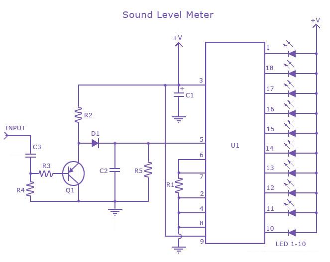 This is a one chip sound level meter that can be use for displaying sound level of an amplifier or simply the sound level from a microphone.The heart of the circuit is IC LM 3915 Audio level IC.Even though it is a stand alone IC , a peak detector based on Transistor BC 558 and diode 1N4001 is also included for better performance.
Supply voltage can be from 3V to 20V.The input is set for audio line voltage (1V peak to peak) and has a max input voltage of 1.3V. To make the circuit use a moving dot display instead of bar graph display,Pin 9 can be should be disconnected from +V.
Part List
C1 2.2uF 25V Electrolytic Capacitor
C2, C3 0.1uF Ceramic Disc Capacitor
R1, R3 1K 1/4W Resistor
R2 10K 1/4W Resistor
R4 100K 1/4W Resistor
R5 1M 1/4W Resistor
D1 1N4001 Silicon Diode
Q1 BC 558 PNP Transistor
LED1-LED10 Standard LED or LED Array
U1 LM3915 Audio Level IC
MISC Board, Wire, Socket For U1


Monday, May 13, 2013
Discrete Virtual Ground Circuit

Thursday, April 11, 2013
IR Remote Control Circuit using Op amp 741
very much popular now-a-days. It is specially called cordless circuit.
This circuit is very simple and low cost cordless remote control circuit
which is based on infrared rays.


fall on the photo-transistor T1 of the receiver, then base of the
photo-transistor’s base produces charge carriers at a rate depending on
the rate of arrival of incident radiations at
the pn junction of the transistor. Then the resulting emitter voltage
is amplified by Op amp IC-2 . The amplified signal is rectified by D2.
Finally the amplified signal is to drive the relay.

Sunday, March 24, 2013
Master Slave Switch Circuit
In this age of enlightenment any sort of relationship that could be described as master/slave would be questionable but for the purposes of this circuit it gives a good idea of how it functions. The circuit senses mains current supplied to a ‘master’ device and switches ‘slave’ equipment on or off. This feature is useful in a typical hi-fi or home computer environment where several peripheral devices can all be switched on or off together. A solid-state relay from Sharp is an ideal switching element in this application; a built-in zero crossing detector ensures that switching only occurs when the mains voltage passes through zero and any resultant interference is kept to an absolute minimum.
Circuit diagram:

Master/Slave Switch Circuit Diagram
All of the triac drive circuitry (including optical coupling) is integrated on-chip so there are very few external components and no additional power supply necessary. This makes the finished design very compact. Diodes D1, D2, D3 and D4 perform the current sensing function and produce a voltage on C2 when the master equipment is switched on. A Schottky diode is used for D5 to reduce forward voltage losses to a minimum. The circuit is quite sensitive and will successfully switch the slave even when the master equipment draws very little mains current. The RC network formed by R1 and C1 provides some protection for the solid-state relay against mains-borne voltage transients.
Warning:
This circuit is connected to the mains. it is important to be aware that the chip has lethal voltages on its pins and all appropriate safety guidelines must be adhered to! This includes the LED, for safety it must be fitted behind a transparent plexiglass shield.
Author: Karl Köckeis - Copyright: Elektor July-August 200
Source : www.extremecircuits.net