Friday, November 2, 2012
Bent Dipole Antenna


Audible Logic Probe Circuit Schematic
 Audible Logic Probe Circuit Schematic Diagram
Automated Digital Camera Shutter

In 1984 I made a camera trigger to capture transient phenomena. I had a Mamiya ZE 35mm camera and Mamiyalite ZE flash unit. Common for bodies of its time, the only indicates of remotely triggering the camera was the cable release socket built into its shutter release button. This was meant to get employed having a purely mechanical cable; it allow you to operate the shutter release from a smaller distance away, and inside a manner that avoided introducing vibration towards the camera at the moment a image was taken. My remedy for releasing the shutter electrically was to make a solenoid set off. I rewound the coil of a little solenoid so that it could produce the required force when operated at 9V. It had been a retraction sort solenoid, which means that applying current to it pulled the armature in. I needed an extension solenoid, so I drilled a hole within the rear of it. I removed the camera end from a cable release - the component that screws to the cable release hole - and soldered it to the rear. I drilled a hole inside the finish of your armature, lower the pusher end from the cable that was part of the release, soldered that in to the armature, and then fed the pusher down through the solenoid and out the finish from the cable release.
The entire thing was light sufficient that I could basically screw it onto the shutter release of the camera and it would be supported with out depressing the button. The other end of the solenoid was threaded for mounting in the way it absolutely was initially designed for. I found a cap that might match this thread. This turned out to get particularly useful, because if set for automated coverage, the camera required that the shutter release be partially depressed for lengthy enough for it to complete its calculation. If the shutter release was basically slammed down as fast since the solenoid did it, the shutter was launched instantly and with incorrect coverage. By adjusting how far I screwed the cap down I could make the shutter release be originally depressed far enough to activate the camera. To run the solenoid I created a circuit that might briefly use present to it when triggered. Additionally, it had a “test” place that will operate a sounder as an alternative to the solenoid, to facilitate setup. I ended up using this program mainly for taking photos of rockets lifting off.
The products that I utilised together with the trigger integrated hardwired circuits and an ultrasonic remote. The ultrasonic remote is at left. I created it with a pair of surplus forty kHz transducers. The green extension cord at proper has an inline switch to set no matter whether units plugged in to the mini jack on the end operate as normally-closed or normally-open triggers. The equipment using the bolt was utilized to consider the tennis-ball cannon pictures beneath.
300 Watt MOSFET Broadband Amplifier Using MRF141G

I recommend getting the two transformer assemblies, instead of trying to create them, due to the fact 15-ohm hardline is not straightforward to come across. I've had great results ordering them from:
RF power techniques
17827 North 26th St.
Phoenix, AZ 85032
1-602-867-0389
The component numbers are TUI-9F and TUO-9F along with the price is about $20 each and every.
This amplifier has the notable attribute of variable acquire manage via the bias adjustment trim pot. It may possibly be used in conjunction with an SWR bridge circuit to limit energy output inside the event of large SWR triggered by harm towards the antenna in the course of a storm, or a person inadvertently disconnecting the coax transmission line. For those who wish to apply a failsafe shutdown system that is triggered by reduction of PLL lock, I nevertheless suggest a power provide cutoff relay for total basic safety having said that.
CAUTION: This amplifier operates at very high power ranges. You are able to obtain severe RF uses up if coming in contact with open coax feeder from this amp. Moreover, if your broadcast antenna is roof-mounted, and it need to blow down inside a windstorm although fed at full power from this amp, it may possibly commence a fire in certain sorts of roofing insulation! Be extremely cautious with all the utilization, set up and operation in the unit.
10V Switching Regulator Using LM5007
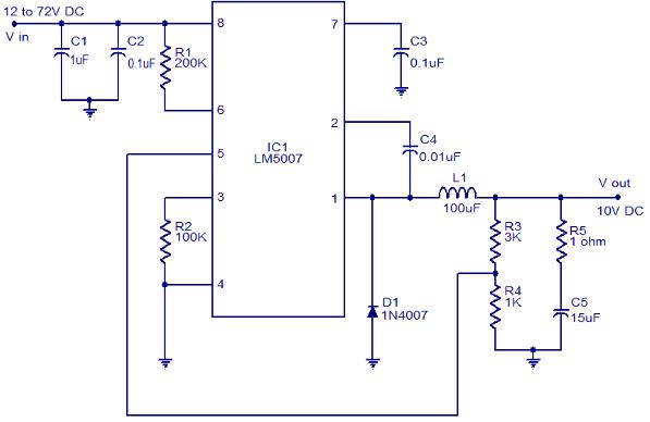 10V Switching Regulator Using LM5007 Circuit Diagram
The circuit diagram shown here is of a 10V switching regulator based on the LM5007 from National Semiconductors. The LM5007 is an integrated step down switching regulator which has all necessary systems required for making a cost effective and reliable switching regulator circuit. The IC is available in MSOP-8, LLp-8 packages and has a lot of built in features like thermal shut down, under voltage lock out, duty cycle limiting, current limiting etc.
The output voltage of this regulator can be adjusted using the resistor R3 and R4. For the given values of R3 and R4 in the circuit diagram, the output voltage will be 10V. The equation governing the output voltage is Vout = 2.5 x (R3+R4)/R4. Resistor R1 sets the switch on time and C4 is the boost boot strap capacitor. Resistor R2 determines the variation of OFF time and C3 is a decoupling capacitor.
Notes.
* The supply voltage can be anything between 12 to 72V DC.
* Output voltage can be adjusted using R3 and R4.
* C1 and C5 are polyester capacitors.
* C1 and C2 must be rated at least 100V.
* R5 and C5 forms a filter network.
* The output current limit of LM5007 is 700mA.
Graphic Equalizer Schematic 10 band Mono

Graphic Equalizer Schematic 10 band Mono Part List: |
| R1....20= 10Kohms | C4= 10nF polyester | C18= 68pF polysterine |
| R21....40= 1Mohms | C5= 47nF polyester | C19= 360pF polysterine |
| R41= 10Kohms | C6= 4.7nF polyester | C20= 36pF polysterine |
| R42= 1Kohms | C7= 22nF polyester | C21= 4.7uF polyester |
| R43.....52= 2.2Kohms | C8= 2.2nF polyester | C22-23= 33pF polysterine |
| R53.....62= 47Kohms | C9= 12nF polyester | C24= 10uF 25V |
| R63-64-66-67= 47Kohms | C10= 1.2nF polyester | C25-26= 47uF 25V |
| R65= 10Kohms | C11= 5.6nF polyester | C27...32= 47nF polyester |
| R68-69= 47 ohms 1/2W | C12= 560pF polysterine | IC1...3= TL074 |
| RV1....10= 100Kohms lin FADER | C13= 2.7nF polyester | S1= 2X4 SW for stereo |
| RV11= 10Kohms log. | C14= 270pF polysterine | |
| C1= 180nF polyester | C15= 1.5nF polyester | |
| C2= 18nF polyester | C16= 150pF polysterine | |
| C3= 100nF polyester | C17= 680pF polysterine |
Honda Motorcycle CB400 (Hawk II) Wiring Diagram
 Honda Motorcycle CB400 (Hawk II) Wiring Diagram
Honda Motorcycle CB750F Wiring Diagram
 Honda Motorcycle CB750F Wiring Diagram
Microphone FM Transmitter Wireless Two Transistors Circuit
 Microphone FM Transmitter Wireless Two Transistors Circuit
Mosfet Audio Amplifier 20W
