Friday, May 31, 2013
Expert Adaptation Main

An Expert Would Think About The Necessary Adaptation From The Xlr Main.

Wiring Diagrams For 12v Led Lighting Elemental Led Academy.

An Xlr To Rj45 Adaptor Will Allow The Use Of Cat5 Cable For.

Wiring You Could Buy A Glm 100 Microphone Which Already Has An Xlr.

Xlr Wiring Xlr Pinout Diagram Jpg.

Figure 6 Pin Assignment Of The Can Bus Cable.

Trs Wiring Diagram.

Interfacing Professional Microphones To Computer Sound Cards.

Parts Express Xlr Connector Wiring Diagram.

Help Wiring Insert Cables Gearslutz Com.

Friday, May 17, 2013
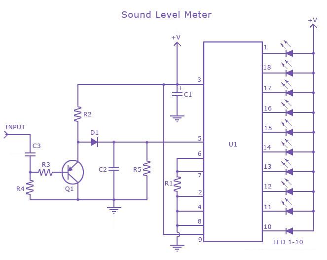
LM 3915 Sound Level Meter Circuit
 This is a one chip sound level meter that can be use for displaying sound level of an amplifier or simply the sound level from a microphone.The heart of the circuit is IC LM 3915 Audio level IC.Even though it is a stand alone IC , a peak detector based on Transistor BC 558 and diode 1N4001 is also included for better performance.
Supply voltage can be from 3V to 20V.The input is set for audio line voltage (1V peak to peak) and has a max input voltage of 1.3V. To make the circuit use a moving dot display instead of bar graph display,Pin 9 can be should be disconnected from +V.
Part List
C1 2.2uF 25V Electrolytic Capacitor
C2, C3 0.1uF Ceramic Disc Capacitor
R1, R3 1K 1/4W Resistor
R2 10K 1/4W Resistor
R4 100K 1/4W Resistor
R5 1M 1/4W Resistor
D1 1N4001 Silicon Diode
Q1 BC 558 PNP Transistor
LED1-LED10 Standard LED or LED Array
U1 LM3915 Audio Level IC
MISC Board, Wire, Socket For U1
Monday, May 13, 2013
Discrete Virtual Ground Circuit
Here is the simple virtual ground circuit based on discrete components.The transistors can be most any complementary pair of small-signal transistors. Suitable alternatives are the PN2222A and PN2907A. The diodes are generic small-signal types. An acceptable alternative is the 1N914. This circuit has better performance than a simple resistive divider virtual ground, and the parts cost is lower than for any other circuit mentioned here. It is, however, the least accurate of the buffered virtual ground circuits.


Sunday, May 5, 2013
Simple Multivibrator Flasher

the basic 2 LED astable multivibrator flasher built by Mary. She chose to use 2 different colored LEDs and the red LED is clear when unlit. It is quite bright when lit compared to the yellow LED despite the fact that it only draws 0.5 mA more. The bread boarded test circuit was powered by a new 9 volt battery and was regulated by a L78L05 (in a TO-92 package as shown in the schematic). The 5 volt regulator was used to avoid exceeding the reverse breakdown voltage of the 2N3904. This topic will be discussed a little later on.
470 ohm current dropping resistors were chosen to keep the collector current draw less than 10 mA. The LEDS were bright enough to see well in dim lighting. You may change this resistor "R" value (lower R = brighter), but do not exceed the maximum current rating for the LED or transistor (this is more applicable to higher voltage multivibrators). You may also place 2 or more LEDs in series on each half of a multivibrator, however, the current dropping resistor may need to be reduced to maintain brightness. Consider using a power supply as opposed to battery power for your flashers.
To change the pulse (oscillation) frequency, you can change the base resistor or the timing capacitor values. For example, increasing the capacitor or the base resistor values will increase the time OFF per cycle and thus reduce the oscillation frequency. The oscillation frequency is 60 divided by the sum of the time OFF for each half of the multivibrator. Do not feel you have to use the same timing capacitor for each 1/2 of the multivibrator. Multivibrators with different timing components on each 1/2 are termed asymmetrical.
Over time, some builders sent me emails that they could not get their multivibrator to run. I problem-solved with them and discovered many problems including bad parts, bread boarding errors, the oscillation frequency was too fast to observe, transistors were not saturated during their ON time and failure of the transistors due to excessive current or perhaps even reverse emitter-base breakdown.